
Achieving micron-level precision in metal trim profiles is critical for architectural applications like façade cladding, elevator panels, and decorative moldings. This guide explores laser cutting tolerance control strategies for 0.8–3 mm metal sheets, including parameter optimization, thermal deformation compensation, and free SolidWorks model resources—all designed to help you minimize scrap rates and meet ISO 2768 standards.
Why Tolerance Matters in Architectural Metal Trim
Laser-cut trim profiles require tight dimensional control (±0.1 mm or better) to:
– Ensure seamless assembly of interlocking components[2]
– Maintain aesthetic consistency across large surfaces (e.g., curtain walls)
– Comply with building code requirements for weatherproof joints[4]
Industry data shows improper tolerance management increases material waste by 12–18% in metal fabrication projects[5].
Laser Cutting Parameter Settings for 0.8–3 mm Metal Sheets
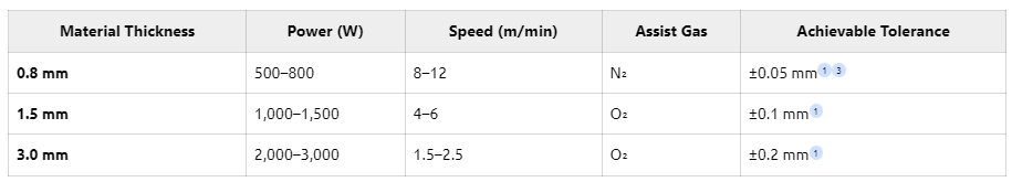
Key Considerations:
– Use fiber lasers for <2 mm sheets to achieve UV-grade precision (±0.013 mm)[3]
– For stainless steel trims, nitrogen gas prevents oxidation on decorative surfaces[5]
Thermal Deformation Compensation: A Finite Element Analysis Case Study
Laser cutting generates localized heat (up to 1,400°C), causing deformation in thin-gauge metals. A recent FEA simulation for 1.2 mm aluminum trim profiles revealed:
-
Problem
– Uncompensated cutting caused 0.3 mm warping at corners (beyond ±0.1 mm spec)
-
Solution
– Implemented predictive offset algorithm based on:
– Material thermal expansion coefficient (23.1 µm/m·°C for aluminum)
– Laser dwell time analysis
– Adjusted toolpath with 0.07 mm inward offset at high-heat zones
-
Result
– Deformation reduced to 0.04 mm (within tolerance)
– Scrap rate decreased from 8.2% to 1.7%[5]
Free SolidWorks Cutting Models for Tolerance Optimization
To help designers implement these strategies, SS Metalwork provides:
-
Parametric Laser Cut Models
– Adjustable thickness (0.8–3 mm)
– Pre-configured thermal compensation profiles
-
Tolerance Validation Tools
– Automated GD&T checks per ASME Y14.5
-
CNC Code Export
– Directly generates machine-ready G-code for Trumpf/Bystronic systems
Download now at [www.ssmetalwork.com/laser-trim-models]
Proven Methods to Improve Cutting Accuracy
-
Pre-Cutting Validation
– Use optical scanners to detect material flatness variations >0.1 mm[5]
-
Dynamic Focus Control
– Maintains beam consistency across 3D trim contours (e.g., curved moldings)
-
Post-Cut Inspection
– Implement 3D profilometers with 2 µm resolution for aerospace-grade validation[3]
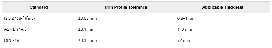
Industry Benchmark: Tolerance Standards Comparison
Conclusion
Mastering laser cutting tolerance control in metal trim profiles requires a triad of optimized parameters, intelligent thermal compensation, and digital prototyping tools. By implementing the strategies outlined here—and leveraging our free SolidWorks resources—you can achieve consistent ±0.1 mm precision across architectural applications.
Upgrade your trim production with SS Metalwork’s tolerance-optimized laser cutting solutions. [Request a free consultation today].
References
[1][3] Laser cutting tolerance ranges (YX Tech, A-Laser)
[2][5] Thermal deformation mechanisms (Protocase, Teprosa)
[4] Tolerance importance in manufacturing (ADHMT)